Improving Locomotive Power Pickup
Although dirty track is a fact of life, its extreme affect on Z-scale locomotives doesn't have to be. By improving the power pickup of a particular engine, you make it less susceptible to the dirt on the tracks that would otherwise interrupt the flow of electricity. The options available to you depend on the locomotive.
In this article:
See also:
I welcome any and all comments, additions, and corrections you wish to email me. Click on any photo to see more detail.
Steam Engines With Tenders
On big steam engines, the driving wheels (which are also responsible for picking up power) are all on a single rigid frame; even the slightest unevenness in the tracks means that one or more wheels won't be in contact, leaving fewer total wheels to pick up power.If you look closely, you'll also notice that only two of the wheels on each side ever actually touch the tracks; the middle wheels are lifted up by the gearing to (theoretically) prevent derailing around curves. Strangely, all wheels are usually in contact when moving in reverse; if there's interest, I may investigate a way to keep all those wheels touching the rails in both directions. At any rate, all this results in fewer wheels touching the tracks at any given time. Big diesels and electrics have two trucks which pivot and turn, which do a much better job of keeping all the wheels in contact with the tracks.
The solution is to add electrical contacts to the remaining wheels, such as those on the tender (I'm working on a way to add contacts to some of the leading and trailing wheels on steam engines without tenders).
|
Commercial Power-Pickup Kits See ZTrains.com for a detailed review of Richmond Controls' wipers for Z-scale rolling stock, complete with close-up photos and an excellent writeup.Schmidt Modelleisenbahn provides a service that adds extra power-pickups to tenders and installs traction tires on the drivers. |
Until Marklin starts shipping their steam engines with additional power pickups, here's an example of how to add power contacts to a tender:
 The first step is to determine where the contacts will go.
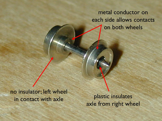
Most tenders use the standard metal wheelsets found on nearly all Marklin rolling stock, as shown in the photo.
These wheelsets are designed to work with electrical contacts in two different ways.
The first step is to determine where the contacts will go.
Most tenders use the standard metal wheelsets found on nearly all Marklin rolling stock, as shown in the photo.
These wheelsets are designed to work with electrical contacts in two different ways.
The first way, used on lighted rolling stock (e.g. Marklin 8738), utilizes a thin copper contact that brushes against the center of the axle. Now, these wheelsets are not symmetrical: only one of the wheels in electrical contact with the axle. With a four-axle tender, two wheels would be used to conduct electricity from the left rail, and two would conduct from the right. This is the easiest method.
The alternative is to use the protrusions on each wheel (the upper red arrows) to have two contacts on each wheelset, effectively doubling the conductivity of the tender. This is what's used on the Marklin 8817 railbus car. In that it requires twice as many contacts, each one needing more careful alignment, this is not only the more difficult method, but it results in twice as much friction.
Note that some tenders have spoked wheels which aren't designed to pick up electricity.
In this case, you can replace the wheels with standard ones, or attach contacts that rub against the rims instead of the axles.
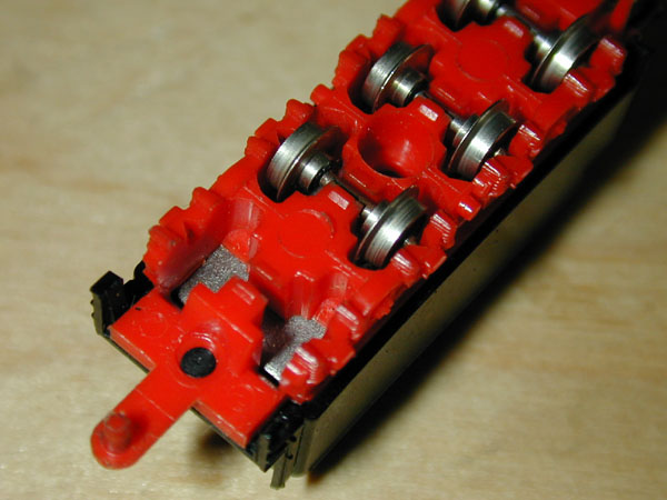 Assuming the tender with which you're working has standard wheels, the next step is to take it apart.
Remove all the wheels, and then carefully trim the black plastic pegs that hold the shell on the red chassis, and pull off the shell.
(While most tenders are similar to this one, some (like American models) have pivoting trucks, which obviously makes this more complicated.)
Assuming the tender with which you're working has standard wheels, the next step is to take it apart.
Remove all the wheels, and then carefully trim the black plastic pegs that hold the shell on the red chassis, and pull off the shell.
(While most tenders are similar to this one, some (like American models) have pivoting trucks, which obviously makes this more complicated.)
The number and specific placement of the contacts is dictated by the design of the tender and your skills. You'll probably want to glue them to the top surface of the chassis, and then bend them down so that they brush against the wheelsets.
First, solder the wires to the new copper contacts, being careful not to harm any surrounding plastic. You may choose to do this soldering before attaching the contacts.
When you attach the wires to the locomotive, solder them to contacts on the frame, but not to the motor or the brushes. Make sure to observe correct polarity - the wires that connect to the left rail should connect to the left side of the locomotive, and so-on. Include enough wire to allow the tender to move around - any excess wire can be shoved up into the tender shell.
ICE 8871 / 88711 Sets
Although ICE sets have two engines, diodes installed in the engines disable most of the power-pickup advantage gained by having two powered units. In addition, the power connection between the two powered units is a little shaky, making these trains less than stellar performers.The good news is that there is the eqivalent of an untapped goldmine in each of the intermediate cars. Each intermediate car that comes with the set, as well as each separately-purchased intermediate car (Marklin 8771) has power pickups in the trucks that connect to the lights. In order to maintain good behavior through blocks of isolated track, however, the power pickups in the cars are separated from the power conduits that travel through each car and connect the engines! If you connect the cars to the engine power, you'll not only drastically improve power pickup for the engines, but you'll put an end to the flickering lights in the intermediate cars.
This is a fairly easy and non-destructive upgrade, and should cost less than a dollar to upgrade the entire train.
 Choose an intermediate ICE car, and pull off the shell.
One of the advantages of this solution is that you can perform it on as many or as few cars as you like; the more, the better.
Choose an intermediate ICE car, and pull off the shell.
One of the advantages of this solution is that you can perform it on as many or as few cars as you like; the more, the better.
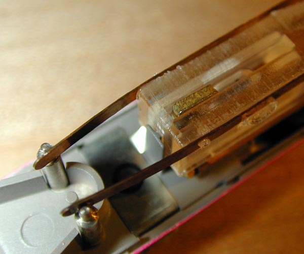 Under the hood, you'll find two copper contacts connecting the front and rear couplers.
The contacts are attached to a plastic light diffuser, and are sprung against the metal poles on each end.
Under the hood, you'll find two copper contacts connecting the front and rear couplers.
The contacts are attached to a plastic light diffuser, and are sprung against the metal poles on each end.
Lift the defuser to reveal the two light bulbs and circuit board, and then remove the two light bulbs.
The circuit board (which connects the two lights and the two trucks) is held in with a slight friction fit, so it can be removed by lifting gently.
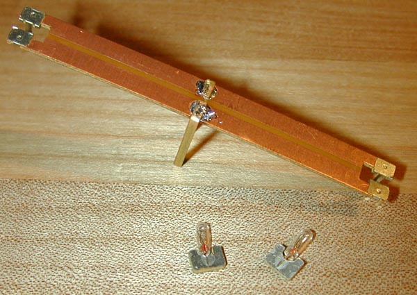 Turn the circuit board upside-down - this is where we'll be attaching the contacts.
I used the smallest, thinnest copper stock my local hobby shop carried - a 12-inch piece certainly didn't cost more than 50 cents.
Turn the circuit board upside-down - this is where we'll be attaching the contacts.
I used the smallest, thinnest copper stock my local hobby shop carried - a 12-inch piece certainly didn't cost more than 50 cents.
Cut two 1-inch segments, and carefully solder them to the bottom of the circuit board as shown in the photo. If you're modifying a supplimental intermediate car (8771), put the contacts exactly in the center so that they will be obscured by the window pillars on the car shell. If you're modifying one of the intermediate cars that comes with the set, put the contacts slightly off center - measure the offset to completely hide the new contacts.
Use a pair of pliers to hold the soldered joints, and carefully bend the two contacts 90o upward.
The bends should be right against the circuit board so they don't stick out too far.
 Place the circuit board back into the car chassis, and re-insert the lights.
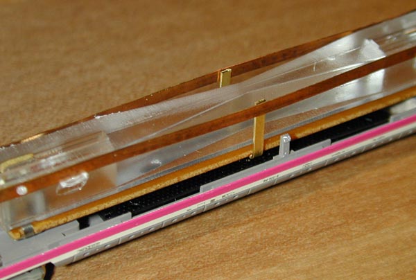
Reattach the diffuser/conduit assembly by pinching the horizontal contacts so that they fit between the poles on each end of the car - at the same time, gently pinch the two vertical contacts you just soldered so that they fit inside the horizontal contacts.
When the diffuser assembly is secure, cut the excess contacts so that they are flush with the top of the diffuser, as shown in the photo.
Place the circuit board back into the car chassis, and re-insert the lights.
Reattach the diffuser/conduit assembly by pinching the horizontal contacts so that they fit between the poles on each end of the car - at the same time, gently pinch the two vertical contacts you just soldered so that they fit inside the horizontal contacts.
When the diffuser assembly is secure, cut the excess contacts so that they are flush with the top of the diffuser, as shown in the photo.
TEE 8873 / 88731 / 88732 Sets
See Improving Marklin Multi-Unit Wiring for details on making minor wiring modifications to improve the way these multi-locomotive trains pick up power.
Marklin 8851 / 81418
If you have a Marklin 8851 (Swiss Federal Railways class Ae 3/6II) or the 81418 set, the 8851 Upgrade Kit from Freudenreich Feinwerktechnik is worth a look.
Marklin Railbus 8816 / 88161 / 88162 / 88163 / 8831
Since all these units travel in pairs, and the dummy units all have lights (which means they already have power-pickups), all that is left is to connect them to eachother. This will help them run smoother, and will help the lights to stay lit more constantly. See the instructions for connecting a steam locomotive to its tender, above, for details.
Marklin F7 Diesels
See Multi-Unit Locomotive Wiring for details on improving the performance of an existing multi-unit locomotive, and details on wiring two single units together. Wiring two powered units together will yield much better power pickup than two individual units. If you have a dummy F7, it can also be wired to the powered unit to achieve the same power-pickup benefit.
Micro-Trains F7 Diesels
Glen Chenier (TeeterTotterTreeStuff.com) sells WheelWipers, little electrical conductors designed to improve the power transmission between the wheels and trucks of Micro-Trains locomotives. An extensive description and detailed installation instructions (with photos) can be found here.
Return Home | Search | Contact Me
Copyright © 2000-2010 D. A. Karp. All rights reserved.