Converting Turnouts to Under-table Drive
When I first starting installing Marklin turnouts on my layout, the black solenoid mechanisms didn't really bother me. And given the investment I had made in these expensive little gadgets, the last thing I wanted to do is tear them apart. So, I installed them as-is.
After a few months, I've come to understand how temperamental and unattractive these units really are. So, I decided to remove the solenoid mechanisms of my turnouts, and convert them to under-table drive. This not only has the affect of making the turnouts look much more prototypically accurate, but since I'll be using larger, more robust, and more easily-accessible solenoids, it makes them more reliable.
This, of course, involves permanently and irreversibly marring these rather expensive and fragile components. As for the cost, I rationalize it this way: by modifying and tweaking these turnouts, I'm making the most of the money I've already spent. See Stop Turnout & Double-Slip Switch Derailing for more alterations to turnouts.
Although the straight turnouts discussed here are the most common Marklin solenoid-equipped track mechanisms, the same process can be applied to the others as well.
In this article:
See also:
I welcome any and all comments, additions, and corrections you wish to email me. Click on any photo to see more detail.
Straight Turnouts
 One thing that made the decision to proceed so much harder is that I've already ballasted all my track, including all 22 turnouts (details here).
So, my first step is to remove some of the ballast so the turnouts can be removed.
One thing that made the decision to proceed so much harder is that I've already ballasted all my track, including all 22 turnouts (details here).
So, my first step is to remove some of the ballast so the turnouts can be removed.
 Using a razor blade, and X-acto knife, and a pick, I carefully broke up the ballast around one side of the turnout.
The ballast stuck well to the baseboard and cork roadbed, but barely at all to the plastic ties on the track and turnout.
Using a razor blade, and X-acto knife, and a pick, I carefully broke up the ballast around one side of the turnout.
The ballast stuck well to the baseboard and cork roadbed, but barely at all to the plastic ties on the track and turnout.
Now, the Woodland Scenics Ballast Cement I used is water-soluble, meaning that water can be used for removal as well as application. If you fully saturate the ballast and then wait about 10-12 hours (don't wait too long, or it will just dry again), the ballast should be soft, plyable, and easier to remove. If you're not the patient type, you can skip the moisture process as I did and just start picking away at the dry ballast.
I also removed two of the track nails holding down the track to the right of the turnout (turnouts should not be nailed down themselves; they should be allowed to "float"), and pulled the turnout out, leaving the two remaining tracks in place.
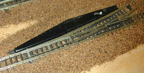
 After removing the turnout from the layout (notice how clean it is, ballast-wise), I unscrewed the cover from the solenoid mechanism.
 Using a small slotted screwdriver, un-bend the four tabs that hold the solenoid to the plastic frame, and gently pull it out.
If you wish to save the solenoid mechanism for use under the table (as opposed to a third-party alternative), be very careful not to break the tiny wires that connect the three metal plates to the solenoid windings. When the solenoid has been safely removed, wrap it tightly with a piece of electrical tape, making sure to keep the three metal plates separate. Don't forget the paper insulator.
Pop out the brass nut, too.
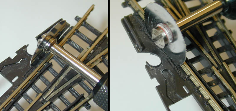 Using a Dremel tool and an ultra-thin saw blade (I used a Forney Industries #60230 5/8" saw), cut the frame along the edges of the ties.
The thin blade is very useful here because it cuts without distorting or melting the plastic, and affords quick and precise cuts.
Cut away the entire frame, except the area around the clear plastic lever (see below).
Using a Dremel tool and an ultra-thin saw blade (I used a Forney Industries #60230 5/8" saw), cut the frame along the edges of the ties.
The thin blade is very useful here because it cuts without distorting or melting the plastic, and affords quick and precise cuts.
Cut away the entire frame, except the area around the clear plastic lever (see below).
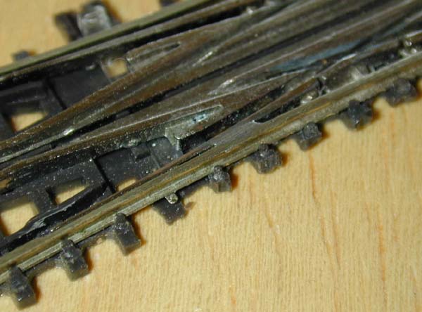
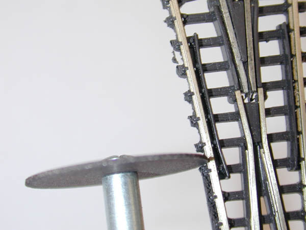 Next, I used a Dremel 420 cut-off disk to carve away the last bits of the frame, leaving only the ends of the ties.
I used a flex-shaft with the Dremel so the disk was always perpendicular to the rails, allowing me to make the cuts more uniformly.
I also held the tool so that the disk always cut in a downward direction, making clean-up with an X-acto knife easy.
Next, I used a Dremel 420 cut-off disk to carve away the last bits of the frame, leaving only the ends of the ties.
I used a flex-shaft with the Dremel so the disk was always perpendicular to the rails, allowing me to make the cuts more uniformly.
I also held the tool so that the disk always cut in a downward direction, making clean-up with an X-acto knife easy.
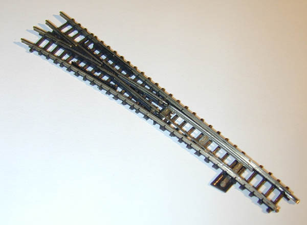 The finished turnout - notice that the portion of the frame around the clear plastic lever was retained to make a frame for the ground throw.
The results around the ties aren't flawless, but the ballast will mask any imperfections.
The finished turnout - notice that the portion of the frame around the clear plastic lever was retained to make a frame for the ground throw.
The results around the ties aren't flawless, but the ballast will mask any imperfections.
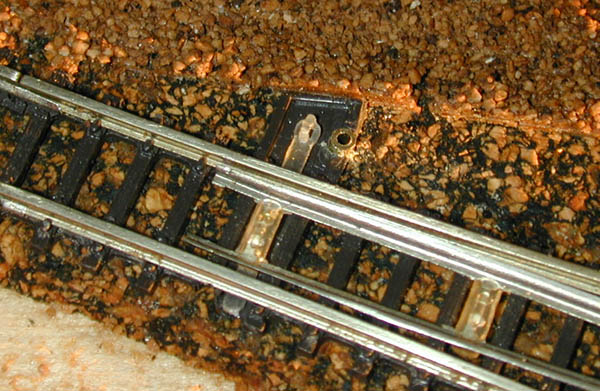 After mounting the turnout back on the layout, I drilled a hole through the edge of the ground throw frame and the baseboard using a #55 drill bit.
I inserted a 15/16"-long piece of a 1/16"-diameter brass tube through the bottom; the #55 bit made the hole just the right size so the tube didn't need any glue.
After mounting the turnout back on the layout, I drilled a hole through the edge of the ground throw frame and the baseboard using a #55 drill bit.
I inserted a 15/16"-long piece of a 1/16"-diameter brass tube through the bottom; the #55 bit made the hole just the right size so the tube didn't need any glue.
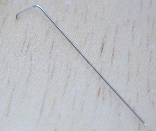
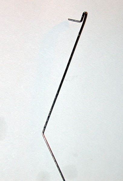 The ground throw was made from a piece of 0.012" stainless steel wire (Detail Associates #3504), bent as shown in the photo.
The arm only needs to be about 1/8" of an inch long, which ends up with about 45o of motion to completely move the points.
I also bent it up and then down to fashion the ground throw, as shown in the photo in the next step.
The ground throw was made from a piece of 0.012" stainless steel wire (Detail Associates #3504), bent as shown in the photo.
The arm only needs to be about 1/8" of an inch long, which ends up with about 45o of motion to completely move the points.
I also bent it up and then down to fashion the ground throw, as shown in the photo in the next step.
It's important to note here that some sort of spring mechanism must be used, strong enough to hold the points in place, but soft enough to allow the points to be displaced by rolling stock coming from the inactive branch.
The 0.012" wire takes care of this nicely; anything thicker is just too rigid.
Detail associates also makes 0.010" wire, which is just a little more flexible and "springy" than the 0.012" wire; you may want to experiment with both weights to get optimal performance from your turnouts.
Avoid brass, as it's soft and may bend over time - stainless steel is very resilient.
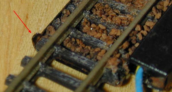
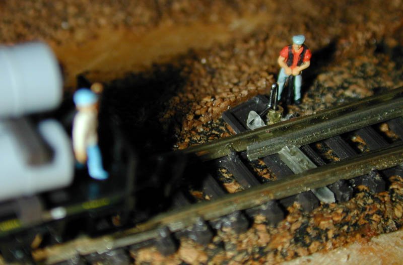 The ground throw was inserted into the brass tube and the arm carefully inserted into the plastic lever.
I think the height is about right: 0.10", or about waist-high to the little man.
(The ground throw in the photo is made with 0.019" wire, and has since been replaced with 0.012" wire, as discussed above.)
The ground throw was inserted into the brass tube and the arm carefully inserted into the plastic lever.
I think the height is about right: 0.10", or about waist-high to the little man.
(The ground throw in the photo is made with 0.019" wire, and has since been replaced with 0.012" wire, as discussed above.)
Under the table, the wire is then bent 90o.
The length of the under-the-table arm will be dependant on the solenoid mechanism I end up using.
Some have suggested Atlas N-scale turnout mechanisms, but I'm still doing my research.
Prototypical speed would sure be nice...
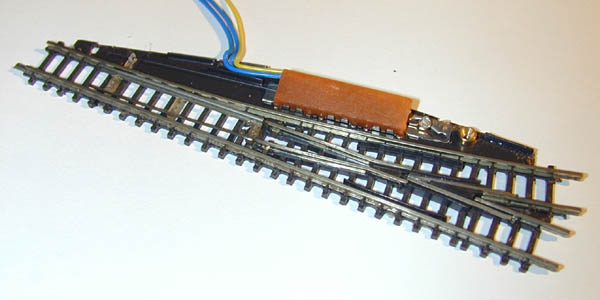
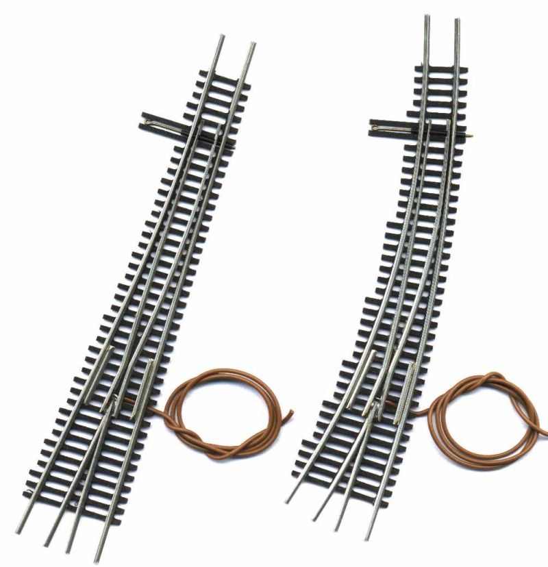
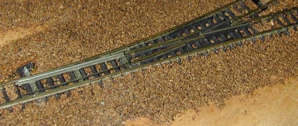 Here's the finished turnout, full linked up, ballasted, and ready to go.
I will probably be gluing a little diamond-shaped flag to the throw to match the real-life ground throws I see around where I live. On the other hand, I may end up redoing the wire as I learn more about ground throws - luckily, it's easy to remove.
Once I've finalized the ground-throw design, I will repeat the process for my other turnouts, and will re-ballast where needed.
Curved Turnouts
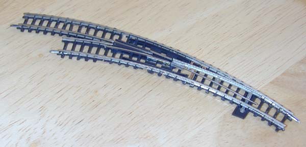 Converting curved turnouts (Marklin 8568 / 8569) is done in pretty much the same way as straight turnouts, above.
The main exception is the extra plastic bulge on the outside of the curve which houses the wire contacts.
(This design has always perplexed me, as it seems superfluous - the wires could just as easily be connected near the solenoid on the other side of the turnout.)
Converting curved turnouts (Marklin 8568 / 8569) is done in pretty much the same way as straight turnouts, above.
The main exception is the extra plastic bulge on the outside of the curve which houses the wire contacts.
(This design has always perplexed me, as it seems superfluous - the wires could just as easily be connected near the solenoid on the other side of the turnout.)
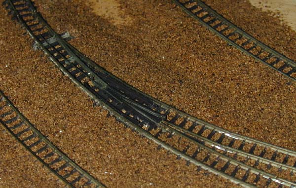 Once you've modified the unit, wire and undertable solenoid hookup is done just like with the straight turnouts, above.
The photo shoes the finished curved turnout, installed and ballasted.
Once you've modified the unit, wire and undertable solenoid hookup is done just like with the straight turnouts, above.
The photo shoes the finished curved turnout, installed and ballasted.
Double slip-switches
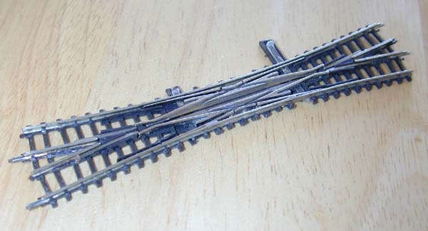 Double-slip switches (Marklin 8560) are substantially more complex than the straight or curved turnouts, discussed above.
Instead of a single plastic lever controlling one pair of points, the double-slip switch has four separate levers attached to four independent points.
Double-slip switches (Marklin 8560) are substantially more complex than the straight or curved turnouts, discussed above.
Instead of a single plastic lever controlling one pair of points, the double-slip switch has four separate levers attached to four independent points.
 One of the nice things about this procedure on double-slip switches is that you can actually make their operation more flexible.
For example, instead of two choices (I'll call them "crossover" and "bypass"), you can have up to eight combinations of point positions.
One of the nice things about this procedure on double-slip switches is that you can actually make their operation more flexible.
For example, instead of two choices (I'll call them "crossover" and "bypass"), you can have up to eight combinations of point positions.
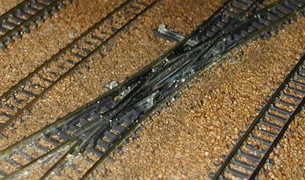
I was lucky with the installation of this unit, because I determined that I needed only two of the points to move; the other two were soldered into position as shown in this photo.
I then removed the clear plastic levers for the soldered points, and kept only the two remaining levers (as shown in the first photo)
 Once you've modified the unit, wire and undertable solenoid hookup is done just like with the straight and curved turnouts, above.
However, you'll have to install a single wire hookup for each of the plastic levers you've left in (up to four).
Then, under the table, all wire levers can be connected together and hooked up to a single solenoid.
Or, you can use multiple solenoids or perhaps some clever wire hookups for more flexible operation.
Once you've modified the unit, wire and undertable solenoid hookup is done just like with the straight and curved turnouts, above.
However, you'll have to install a single wire hookup for each of the plastic levers you've left in (up to four).
Then, under the table, all wire levers can be connected together and hooked up to a single solenoid.
Or, you can use multiple solenoids or perhaps some clever wire hookups for more flexible operation.
As an added bonus, I've found that double-slip switches modified in this way are more reliable (in addition to being more attractive) than they were before their modifications.
The photo shows the finished double-slip switch, installed and ballasted.
Uncouplers
I've found the stock Marklin uncoupler track sections to be rather unreliable, as even the littlest amount of dirt or corrosion will prevent the solenoid mechanism from raising the gray plastic insert. Additionally, the black solenoid box on the uncoupler sticks up a little higher than on the turnouts, and since it doesn't have rounded edges, it can get stuck on some cars (most notably Marklin 8619 wood carrier). This procedure happily fixes both problems!
 Marklin uncouplers (8587 / 8597) are the easiest of the solenoid track mechanisms to modify.
In fact, it can be done with no cutting or permanent marring of any kind!
Start by slightly bending out the five metal tongues on the opposite side of the unit from the solenoid (it's not necessary to do it on both sides).
Marklin uncouplers (8587 / 8597) are the easiest of the solenoid track mechanisms to modify.
In fact, it can be done with no cutting or permanent marring of any kind!
Start by slightly bending out the five metal tongues on the opposite side of the unit from the solenoid (it's not necessary to do it on both sides).
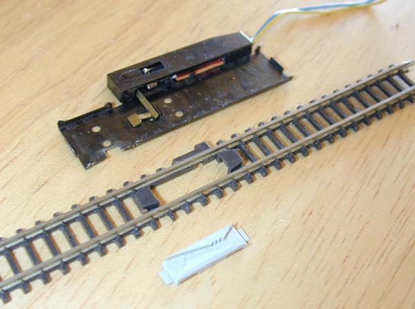 Then, simply pivot and lift out the track from the metal housing.
(I've found that the metal housing is identical for both the full-length 8597 track, now discontinued, and the half-length 8587 track.)
Then, simply pivot and lift out the track from the metal housing.
(I've found that the metal housing is identical for both the full-length 8597 track, now discontinued, and the half-length 8587 track.)
 Before putting the uncoupler track back in place, I took the opportunity to add a magnet under the track for automatic uncoupling of Micro-Trains couplers.
I figured the best place for the magnet was under the Marklin uncoupler track (right next to the uncoupler unit), not only because it's easily identified, but to allow me to uncouple cars in the same place, regardless of the coupler type.
Before putting the uncoupler track back in place, I took the opportunity to add a magnet under the track for automatic uncoupling of Micro-Trains couplers.
I figured the best place for the magnet was under the Marklin uncoupler track (right next to the uncoupler unit), not only because it's easily identified, but to allow me to uncouple cars in the same place, regardless of the coupler type.
I used Micro-Trains (Kadee) #312 HO-scale Magne-matic non-delayed uncouplers, which is simply a package of two 1/8" x 5/16" x 2" ceramic magnets. I chose this product primarily because it's what my local hobby store had in stock, but also because the magnets are larger and more powerful than the smaller ones typically used in N and Z scales. I ended up cutting the two included magnets in half (score with a knife or Dremel and then break over a straight-edge), which not only gave me four magnets (enough for my whole layout), but made them an almost convenient size.
There are a lot of different kinds of magnets available, so before installing them on your layout, test them by setting a long piece of Marklin track on top of the magnet (centered between the rails), and then pushing two coupled Micro-trains cars back and fourth over it. I recommend Micro-Trains (Kadee)-brand magnets for the most reliable uncoupling.
The magnets were just a hair thicker than my cork roadbed, so I used a Dremel 330 router attachment and a Dremel 650 router bit to make room in the baseboard.
The photo shows the magnet installed, flush with the top of the roadbed.
 Just like with the turnouts, above, a piece of 0.012" stainless steel wire (Detail Associates #3504), bent as shown in the photo, was used to actuate the Marklin uncoupler.
Instead of having the undertable solenoid turn the wire, it will need to be connected so that the wire is pushed up to raise the gray plastic insert.
The little bend at the end helps keep the wire from turning and getting caught under the track.
Just like with the turnouts, above, a piece of 0.012" stainless steel wire (Detail Associates #3504), bent as shown in the photo, was used to actuate the Marklin uncoupler.
Instead of having the undertable solenoid turn the wire, it will need to be connected so that the wire is pushed up to raise the gray plastic insert.
The little bend at the end helps keep the wire from turning and getting caught under the track.
You may wish to experiment with different shapes here to get the most reliable results.
 Put the track into position on your layout, but leave out the gray plastic insert.
Drill a hole through the baseboard at the center of the space left by the missing insert using a #55 drill bit, and insert a piece of a 1/16"-diameter brass tube through the hole.
The photo shows the bent wire inserted into the brass tube.
Put the track into position on your layout, but leave out the gray plastic insert.
Drill a hole through the baseboard at the center of the space left by the missing insert using a #55 drill bit, and insert a piece of a 1/16"-diameter brass tube through the hole.
The photo shows the bent wire inserted into the brass tube.
Then, lift up the track slightly, and put the gray plastic insert into position, being careful not to disturb the wire (the bent portion should be roughly parallel to the track rails).
Nail or attach the track as desired at this point.
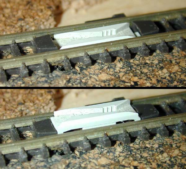 By pushing up gently on the wire under the table, the uncoupler will raise, as shown in the photo.
I haven't yet hooked up a solenoid mechanism to my uncouplers, but when I do, I will include pictures here of the process.
 The photo shows the finished uncoupler, installed and ballasted.
Note that the uncoupler magnet is completely hidden.
The photo shows the finished uncoupler, installed and ballasted.
Note that the uncoupler magnet is completely hidden.
|
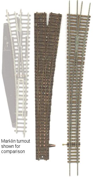
Non-Marklin Turnouts In addition to Marklin turnouts, two other small manufacturers have released more realistic turnouts for Z-scale. Here are some photos of turnouts from Halwa Feinmodellbau and Petau Modellbau. See the Manufacturers page for contact information.One thing to note: Marklin turnouts match Marklin track, so if you are interested in using these other turnouts, you should consider using track by Micro-Trains or Peco. |
Return Home | Search | Contact Me
Copyright © 2000-2010 D. A. Karp. All rights reserved.